What Are Lifting Bolts and How Are They Used?

Lifting Bolts are compact mechanical components designed to create a controlled lifting point on equipment, frames, machinery, and fabricated structures. Their appearance can be deceptively simple. A threaded shank enters a prepared hole, while an eye, shoulder, or forged head receives a hook, sling, or shackle. The connection carries real consequences.

Terminology is not perfectly consistent across suppliers. Some catalogs use “lifting bolt” for a forged eye bolt, while others describe shoulder eye bolts separately. That distinction matters. ISO 3266 covers forged-steel lifting eye bolts, while ASME B30.26 addresses rigging hardware, including identification, inspection, and operating practices. These standards emphasize rated capacity, proper loading, and visible markings. A strong-looking bolt is not automatically a safe lifting device.

The wider material-handling sector also shows why disciplined selection matters. MHI’s 2024 Annual Industry Report identifies safety, workforce capability, and operational reliability as continuing priorities for material-handling companies. In practice, those priorities appear at the worksite: a marked bolt, a clean thread, and a sling aligned with the load. Small details control large forces.

Before using Lifting Bolts, qualified personnel should verify the working load limit, thread engagement, base material, installation direction, and lifting angle. OSHA’s material-handling guidance also requires employers to inspect equipment and protect workers from suspended loads. Never confuse a general-purpose eye bolt with a certified lifting point. Never rely on appearance alone.

This guide explains what Lifting Bolts are, how they function, and where their limits begin. It also examines common installation errors. Some recommendations may seem obvious. They are still often missed.
What Are Lifting Bolts and How Are They Used?

Definition, Components, and Rated Capacity of Lifting Bolts

What Are Lifting Bolts and How Are They Used?

Definition, Components, and Rated Capacity of Lifting Bolts

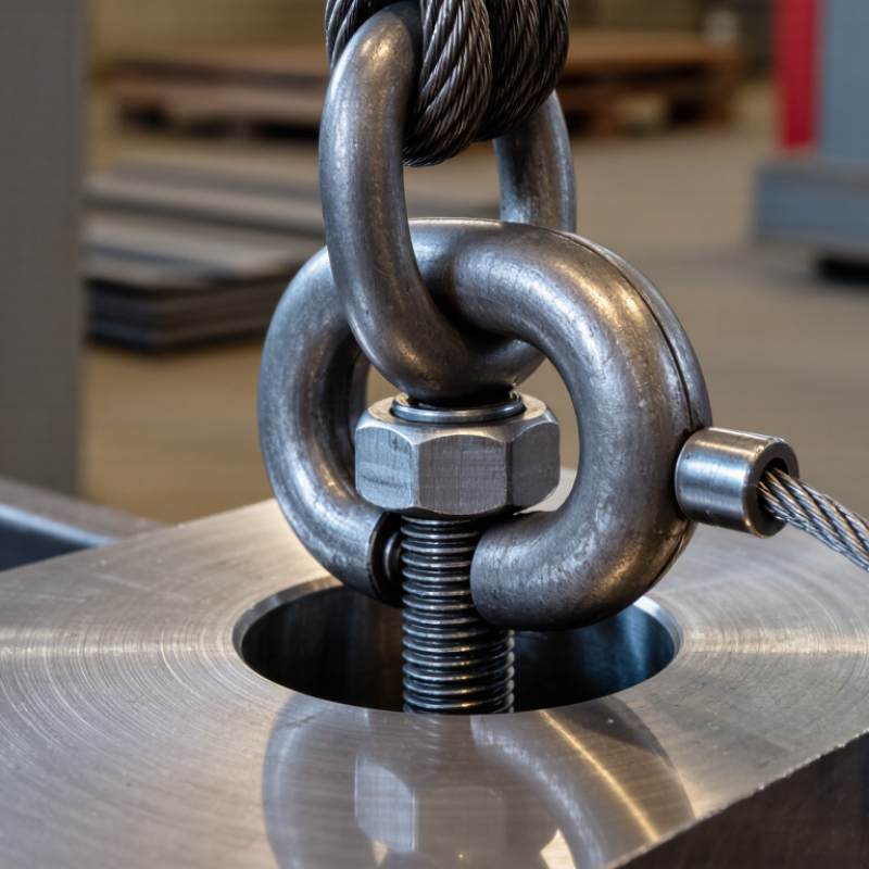
Lifting bolts are engineered fasteners used to attach lifting equipment to a load. Unlike ordinary bolts, they include a lifting feature, such as an eye, ring, or shaped head. This feature connects with hooks, shackles, or slings. The bolt body usually contains a threaded shank, load-bearing shoulder, and forged head. Each part supports a specific function.

The rated capacity is the maximum working load allowed under stated conditions. It is not simply the bolt’s breaking strength. Capacity depends on material, thread size, thread engagement, installation direction, and lifting angle. The supporting base material matters too. A strong bolt can still fail in weak or cracked material. Always check the manufacturer’s marked working load limit and technical data.

Use the bolt only as designed. Install it fully into a clean, correctly sized threaded hole. The shoulder should sit firmly against the load when the design requires it. Avoid side loading unless the product is specifically rated for it. Angled pulls can reduce capacity sharply. Inspect the threads, eye, and shoulder before every lift. Look for bending, cracks, corrosion, or stretched metal. Never replace a lifting bolt with a standard hardware bolt. That shortcut may look harmless. It is not. In practice, unclear markings and poor alignment cause many avoidable errors, so a qualified person should verify the setup before lifting.

Eye, Shoulder, Swivel, and Ring Bolt Designs Compared by WLL

Lifting bolts are threaded lifting points used to raise machinery, molds, frames, and fabricated structures. Their WLL, or Working Load Limit, depends on more than bolt diameter. Thread engagement, steel grade, lifting angle, load direction, and surface condition all matter. ASME B30.26 requires lifting hardware to carry clear identification, including rated capacity or size information. ISO 3266 also emphasizes controlled design, marking, inspection, and testing for lifting points.

Eye bolts suit straight, vertical lifts when the eye stays aligned with the sling. Shoulder eye bolts add a machined shoulder, helping resist bending when installed correctly against a flat surface. They are not automatically safe for side loading. Swivel bolts rotate under load and can follow changing sling directions, which reduces twisting at the connection. Ring bolts use a circular ring and may offer better sling clearance, but their WLL still changes with the loading angle.

Small details decide capacity. A 2-ton WLL may apply vertically, yet the manufacturer’s table can reduce it sharply at 45 degrees or during multi-leg lifting. Never guess from appearance. OSHA 1910.184 requires employers to inspect slings and remove damaged equipment, while practical inspection guidance also checks bent eyes, stretched rings, cracked shoulders, damaged threads, and missing markings. A clean bolt can still be unsuitable. That is the uncomfortable part. Engineers should calculate the complete load path, verify torque and thread depth, and record inspections before each critical lift.

Lifting Bolt Designs Compared by Working Load Limit

Representative vertical-lift WLL values for M12-class lifting hardware. Actual capacity depends on material, thread engagement, installation, loading angle, and the manufacturer’s certified rating.

Shoulder and swivel designs generally provide higher rated capacity than basic eye bolts because they are engineered for more controlled load transfer. Eye and ring bolts must be loaded in line with the bolt axis; side loading or angular loading can substantially reduce the WLL. Always use the certified WLL marked or specified for the exact product.

WLL, Proof Loads, and Design Factors Under ASME B30.26

Lifting bolts are threaded fasteners with an eye or lifting head. They connect a load to a sling, shackle, or hoist. The threaded section must fully engage a suitable tapped hole. Clean threads, correct diameter, and firm seating matter.

Under ASME B30.26, the Working Load Limit, or WLL, is the maximum permitted load for a defined configuration. It is not the bolt’s breaking strength. A lifting bolt may have a different WLL for straight, vertical loading than for angled loading. Side pulling can bend the bolt and sharply reduce capacity. Keep the load aligned with the bolt’s axis whenever possible.

Proof load testing applies a controlled force to verify manufacturing integrity. It does not authorize repeated lifting above the marked WLL. The design factor compares minimum breaking strength with the rated working load. It provides a safety margin for uncertainty, wear, and dynamic effects. However, the actual margin depends on the hardware type and applicable requirements.

Before use, inspect the eye, threads, seating surface, and load path. Look for cracks, corrosion, distortion, or thread damage. Check that the load will not rotate or loosen the bolt. That detail is easy to miss. ASME compliance alone cannot correct poor rigging practice. In real lifting work, unclear markings or unusual loading should stop the lift until a qualified person reviews the setup.

What Are Lifting Bolts and How Are They Used? — WLL, Proof Loads, and Design Factors Under ASME B30.26
Data Dimension Verified Technical Information Practical Example or Requirement
Lifting Bolt Definition A lifting bolt is a load-rated threaded fastener or lifting-point assembly designed to provide a connection point for lifting equipment. It may include an eye, swivel, shoulder, or other load-bearing feature. Use only a lifting bolt that is specifically marked and rated for lifting. A standard hardware-store bolt must not be treated as a lifting bolt.
Primary Function Lifting bolts transfer force from a sling, hook, or other rigging component into the threaded attachment point of a load. The bolt, threads, base material, attachment geometry, and rigging connection must all be capable of carrying the imposed load.
Working Load Limit (WLL) WLL is the maximum permitted working load for a product under the conditions specified by its manufacturer, including the approved direction of loading and installation method. A lifting bolt marked with a WLL of 1,000 kg may be used for loads up to 1,000 kg only when the installation and loading direction meet its rating requirements.
WLL and Mass Conversion For engineering calculations, 1 metric tonne-force equals 9.80665 kN, and 1,000 kg of mass produces approximately 9.81 kN of gravitational force under standard gravity. Load force = mass × 9.80665 / 1,000
Example: 500 kg ≈ 4.90 kN.
Proof Load A proof load is a specified test load applied to verify that a component can withstand the test without unacceptable permanent deformation, cracking, or other damage. It is not the same as the WLL. The applicable product standard, certification basis, or manufacturer’s instructions must define the proof-load value. Do not assume that every lifting bolt has the same proof-load ratio.
Proof-Test Result A successful proof test does not automatically increase the WLL or authorize use outside the product’s marked rating. A component tested above its normal WLL still remains limited to its stated WLL unless formally re-rated by a qualified authority under an applicable standard.
Design Factor The design factor is the relationship between the minimum breaking strength and the rated working load. It accounts for uncertainty, material variation, wear, loading conditions, and manufacturing tolerances. Design factor = minimum breaking strength ÷ WLL
Example: 5,000 kg minimum breaking strength ÷ 1,000 kg WLL = design factor of 5.
ASME B30.26 Relevance ASME B30.26 addresses rigging hardware, including requirements related to identification, inspection, maintenance, operation, and safe use. The exact requirements depend on the hardware type and applicable edition. Use the current edition of ASME B30.26 together with the product documentation and any applicable hardware-specific standard.
Axial Loading Axial loading applies force substantially in line with the intended load axis of the lifting bolt. This is generally the preferred loading direction when the product is designed for it. Align the hook and sling with the lifting axis. Avoid side loading unless the product is specifically rated for that direction.
Angular or Side Loading Angled loading can reduce the allowable capacity and may introduce bending stresses in the bolt, eye, threads, or supporting structure. Do not apply a general angle-reduction factor unless it is provided by the manufacturer or a qualified engineer for the exact lifting bolt and configuration.
Thread Engagement The threaded hole must provide adequate engagement, strength, cleanliness, and alignment for the rated load. Capacity may be limited by the weaker of the bolt, threads, or base material. Inspect for damaged, short, contaminated, cross-threaded, or corroded threads before installation. Follow the specified engagement depth and torque requirements.
Shoulder and Seating For lifting bolts designed with a shoulder, the shoulder must seat correctly against a suitable, flat load-bearing surface when the instructions require it. Do not use spacers, washers, damaged surfaces, or uneven seating arrangements that prevent the shoulder from bearing as designed.
Sling Angle Effect In a two-leg sling, the tension in each leg increases as the angle between the legs becomes wider. A simple symmetrical approximation is: T = W ÷ [2 × cos(θ)]
For a 1,000 kg load with each sling leg 30° from vertical, each leg carries approximately 577 kg of tension, before other effects are considered.
Inspection Before Use Inspect markings, threads, body condition, deformation, cracks, corrosion, wear, thread damage, and evidence of unauthorized modification. Remove from service if the identification is missing or unreadable, if cracks or permanent deformation are found, or if the component has been subjected to shock loading or overload.
Shock Loading Sudden pickup, impact, snatching, dropped loads, or abrupt load transfer can create forces substantially higher than the static load. Lift smoothly, keep the line taut without jerking, and account for dynamic effects in the lift plan.
Temperature and Environment High or low temperatures, corrosive chemicals, marine exposure, and abrasive service can affect material strength and allowable capacity. Apply any temperature or environmental limitations stated in the product documentation. Do not paint over identification markings or conceal damage.
Safe Use Principle The complete lifting system is limited by the component or attachment point with the lowest allowable capacity. Verify the rated capacity of the lifting bolt, sling, shackle, hook, connection, and load structure before lifting.
Important: WLLs, proof loads, design factors, installation torque, angle reductions, and inspection limits are product- and application-specific. Always follow the current ASME B30.26 requirements, the lifting-bolt manufacturer’s instructions, and the approved lift plan.

Installation Steps: Thread Engagement, Alignment, and Torque

What Are Lifting Bolts and How Are They Used?

Lifting bolts are engineered attachment points for raising machinery, frames, or fabricated assemblies. They are not ordinary fasteners. Their threads must fully engage with a rated hole or nut. The International Labour Organization estimated 395 million nonfatal work-related injuries worldwide in 2023. Poor lifting preparation remains one preventable contributor.

Begin by checking the bolt’s markings, working load limit, thread size, and inspection condition. Remove paint, dirt, and damaged threads from the connection. Engage the bolt by hand before using tools. The bolt should turn smoothly without cross-threading. Aim for full thread engagement, with no visible gap between the shoulder and mounting surface. Short engagement is risky. It can concentrate loads near the first threads.

Alignment matters during installation. Position the lifting bolt in line with the intended pull. Avoid side loading, twisting, or sharp sling angles. A washer may be required, but only when the engineered design permits it. Tighten the bolt using the specified torque, a calibrated torque wrench, and clean, suitable threads. Do not guess from hand feel. ASME BTH-1 and ASME B30.26 provide recognized guidance for below-the-hook devices and rigging hardware. Their requirements should be checked against the manufacturer’s engineering data and site procedures.

Inspect the assembly again before lifting. The bolt should remain seated, aligned, and free from cracks or deformation. I would not treat a visually acceptable connection as proven safe; thread condition and load direction still need verification. past experience often exposes that mistake.

Inspection, Load-Angle Limits, and Retirement Criteria for Safe Use

Lifting bolts are engineered attachment points for hoisting loads, not ordinary fasteners. Their working load limit depends on the bolt, base material, thread engagement, and lifting direction. A marked rating is useful only when installation matches the design. Check the technical drawing and load table before connecting slings. Do not guess.

Inspect each lifting bolt before use. Look for cracks, bent shoulders, damaged threads, deep grooves, corrosion, and stretched metal. Check that markings remain readable. The surrounding tapped hole also matters; damaged threads can fail without obvious warning. In practice, dirt and paint often hide small defects. Clean the area carefully, but do not grind away evidence. A recent shock load deserves a closer inspection.

Load angle limits require particular care. Many lifting bolts are rated for a straight pull only, while others permit specific side loading. The allowed angle must come from the design documentation, not a general rule. Angled slings can sharply reduce capacity and introduce bending forces. Keep the load aligned with the bolt whenever possible. Stop using the bolt after visible deformation, cracking, severe wear, overheating, thread damage, or an uncertain overload. Do not straighten, weld, or modify it. Quarantine questionable hardware and have a competent inspector assess it. One overlooked detail can change the entire lifting arrangement.

Request More Information